Advertisement

Create a new regular mesh from vertices

Started by December 06, 2004 09:00 PM
5 comments, last by llvllatrix 19 years, 8 months ago
Currently I have a wavefront(obj) file that contains the 3d coord of all the vertices, its texture coordinates and the faces(forming an irregular triangular mesh). So it is possible to create a new regular mesh using just the 3d coord n texture coord of all vertices? If so, what are the tools to use? The structure of the new regular mesh must of the form: 
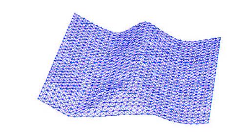
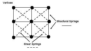
so that is will form a structure something similar to the one below: I would also need the output file to be a wavefront file with the texture coord which I will my c program and opengl to display it. Here is an example of my input obj file -> Link here Thanks in advance. P.S. In another thread, someone has kindly recommended using me Maya to create a mesh and then manually maniupulate it to fit into the geometry of my existing irregular mesh. I will read up on that. Would also prefer something fast and simple to use. :)
Unfortunatly, I'm not starting my linear surface approximation maths course for a few months so I can't tell you [wink]
but that might give you a head start if you google around a bit.

eg http://www.google.com/search?&q=%22Linear%20Approximation%22%20surfaces or such.
Advertisement
Well, I seem to remember your post from before, and while I dont think that this would give you a mathematically PERFECT solution, it might give you one that is darn close. Here is what I would do to solve your problem:

You have your "kinda flattish" Irregular mesh like in your previous thread. IT is composed of a whole bunch of vertices kinda scattered around that make a kind of book shape. All of those together give a surface after they are connected by triangles: What I would do is this: take a flat big rectagle, that is made up of regular squares and is the approximate depth and width of the irregular shape. Put the vertices of the whole thing at a position above your irregular mesh, and then for each of the vertices of the regularlly meshed rectangle, (algorithmically, of course: by hand would suck a lot) Find the place where a vertical line through the vertex would intersect the irregular mesh. You may have to do some planar algebra because of the fact that your lines probably wont intersect the irregluar surface at a specific vertex. Then, the points of intersection should be a new, approximatly regular mesh.

//Irregular mesh                         .      . ...    .    .     .                                                ......//plus regluar rectangle.        .        .         .         .        .       .     .                         .      . ...    .    .     .                                                ......//plus lines .        .        .         .         .        .       .     .|         |        |         |          |        |       |      |   |         |        |         |          |        |       |      ||         |        |      .      . ...    .     |        |      | .     .                                                ......//equals regular mesh                           .             . .        .         .                             .        .      .//YAY!:-)


Anyway, that is my idea at least. If my horrible ASCII art didnt illustrate the concept, At least I tried :-). Good Luck!
Hi,

Your file contains both vertices and tesselation data (that is the realtion between the vertices). You should be able to construct an approximation of the mesh using this data alone (cast a ray vertically at a given x,z point of your regular mesh and have it collide with your irregular; the collision point gives you your y value). The result would be a mesh alligned with the coordinate axis and it would look like someone took a piece of cloth and hung it over your model (there would be overhang).

You might also be able to use the texture coordinates to determine the z value of the irregular mesh. The texture coordinates essentially describe how to map a plane to the model. Basically find the extremes of the texture coordinates (ie the lowest and highest) and sample starting from the lowest and moving towards the highest. At each sample, use interpolation between the vertices of the mesh and their relation to the texture coordinate to determine the x, y, and z of the point. The result would be a regular mesh with no overhang and would be alligned with the trends of your model. Be advised however that the texture coordinates that are in the obj file you provided are overly large (i imported the model into milkshape).

If you manually import the file into a model editor, create your own regular mesh, and then export the result you will still be left with the same information that you began with. That is you will still just get vertices and faces. If you intend to manipulate the mesh then you will still need to go through the process of recreating the regular mesh in order to establish the planar relationship between vertices.

Hope that helps and good luck,
- llvllatrix
Quote: Original post by Steve132
Well, I seem to remember your post from before, and while I dont think that this would give you a mathematically PERFECT solution, it might give you one that is darn close. Here is what I would do to solve your problem:

You have your "kinda flattish" Irregular mesh like in your previous thread. IT is composed of a whole bunch of vertices kinda scattered around that make a kind of book shape. All of those together give a surface after they are connected by triangles: What I would do is this: take a flat big rectagle, that is made up of regular squares and is the approximate depth and width of the irregular shape. Put the vertices of the whole thing at a position above your irregular mesh, and then for each of the vertices of the regularlly meshed rectangle, (algorithmically, of course: by hand would suck a lot) Find the place where a vertical line through the vertex would intersect the irregular mesh. You may have to do some planar algebra because of the fact that your lines probably wont intersect the irregluar surface at a specific vertex. Then, the points of intersection should be a new, approximatly regular mesh.


Anyway, that is my idea at least. If my horrible ASCII art didnt illustrate the concept, At least I tried :-). Good Luck!


Thanks, Steve. Your ASCII is very well-drawn. I can understand your concept. I think at the moment, I just have to think how to code in C. :)
Quote: Original post by llvllatrix
Hi,

Your file contains both vertices and tesselation data (that is the realtion between the vertices). You should be able to construct an approximation of the mesh using this data alone (cast a ray vertically at a given x,z point of your regular mesh and have it collide with your irregular; the collision point gives you your y value). The result would be a mesh alligned with the coordinate axis and it would look like someone took a piece of cloth and hung it over your model (there would be overhang).

You might also be able to use the texture coordinates to determine the z value of the irregular mesh. The texture coordinates essentially describe how to map a plane to the model. Basically find the extremes of the texture coordinates (ie the lowest and highest) and sample starting from the lowest and moving towards the highest. At each sample, use interpolation between the vertices of the mesh and their relation to the texture coordinate to determine the x, y, and z of the point. The result would be a regular mesh with no overhang and would be alligned with the trends of your model. Be advised however that the texture coordinates that are in the obj file you provided are overly large (i imported the model into milkshape).

If you manually import the file into a model editor, create your own regular mesh, and then export the result you will still be left with the same information that you began with. That is you will still just get vertices and faces. If you intend to manipulate the mesh then you will still need to go through the process of recreating the regular mesh in order to establish the planar relationship between vertices.

Hope that helps and good luck,
- llvllatrix


Hi llvllatrix

I think the casting of a ray down is somewhat similar to what Steve suggested. However I am not quite sure how this can be implemented. Would appreciate if you can drop me more hints like how to check for intersection and getting the y value. Btw, I am using Visual c++ for my simulation.

Thanks.

Regards

[Edited by - Mystery on December 23, 2004 7:06:57 PM]
Advertisement
I think in all honesty you should use the second method i mentioned that uses texture coordinates (it would probably give you better results and would also conform better to the surface of the model).

To do the intersection, you could use some of the freely avaliable collision detection libraries. ColDet should be able to handle the task. Simply feed your model into the library and then test it against your vector and the resulting point is your answer.

Good luck,
- llvllatrix

This topic is closed to new replies.

Advertisement