🎉 Celebrating 25 Years of GameDev.net! 🎉

Not many can claim 25 years on the Internet! Join us in celebrating this milestone. Learn more about our history, and thank you for being a part of our community!

PBR/IBL and models locked to camera position (first person assets)

Started by
7 comments, last by CDRZiltoid 2 years, 9 months ago

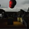
First off, here's a video of what I'm about to explain:

I've managed to get a PBR pipeline setup that's using image based lighting. However I have a question regarding models that are locked to the camera, such as elements of a first person shooter such as arms/weapons/etc. In my particular case, I have a separate camera setup that does not translate via a view matrix so all elements of the first person “Stage” have transforms relative to screen space.

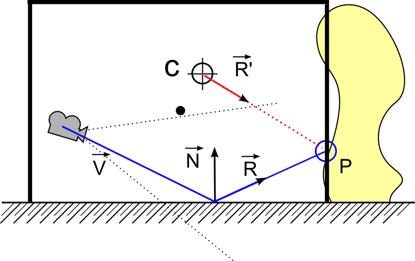
In order to apply the correct IBL information to the assets within this first person stage, I pass an offset matrix which is the inverse of the view matrix of the camera for the world stage, to be used in the fragment shader calculations. Which appears to work as expected. However since the IBL is being calculated relative to the camera position, when moving around the reflectance stays the same (when in reality it would be changing) until rotating as you can see in the video above.

Therefore I suppose my question becomes: Since an IBL cubemap remains fixed, and IBL/reflectance is relative to camera position…how does one accurately calculate light value for model which is fixed to camera?

I will paste my shader code below. Can post additional code upon request.

(removed vertex shader as it wasn't really necessary and was just making the post longer)

fragment shader (essentially a stripped down version of the learnopengl.com pbr shader):

#version 450 core
out vec4 FragColor;
in vec2 TexCoords;
in vec3 WorldPos;
in vec3 Normal;

// material parameters
uniform sampler2D albedoMap;
uniform sampler2D normalMap;
uniform sampler2D metallicMap;
uniform sampler2D roughnessMap;
uniform sampler2D aoMap;

// IBL
uniform samplerCube irradianceMap;
uniform samplerCube prefilterMap;
uniform sampler2D brdfLUT;

uniform vec3 camPos;

const float PI = 3.14159265359;
// ----------------------------------------------------------------------------
// Easy trick to get tangent-normals to world-space to keep PBR code simplified.
// Don't worry if you don't get what's going on; you generally want to do normal 
// mapping the usual way for performance anways; I do plan make a note of this 
// technique somewhere later in the normal mapping tutorial.
vec3 getNormalFromMap()
{
    vec3 tangentNormal = texture(normalMap, TexCoords).xyz * 2.0 - 1.0;

    vec3 Q1  = dFdx(WorldPos);
    vec3 Q2  = dFdy(WorldPos);
    vec2 st1 = dFdx(TexCoords);
    vec2 st2 = dFdy(TexCoords);

    vec3 N   = normalize(Normal);
    vec3 T  = normalize(Q1*st2.t - Q2*st1.t);
    vec3 B  = -normalize(cross(N, T));
    mat3 TBN = mat3(T, B, N);

    return normalize(TBN * tangentNormal);
}
// ----------------------------------------------------------------------------
vec3 fresnelSchlickRoughness(float cosTheta, vec3 F0, float roughness)
{
    return F0 + (max(vec3(1.0 - roughness), F0) - F0) * pow(max(1.0 - cosTheta, 0.0), 5.0);
}  
// ----------------------------------------------------------------------------
void main()
{		
    // material properties
    vec3 albedo = pow(texture(albedoMap, TexCoords).rgb, vec3(2.2));
	float alpha = texture(albedoMap, TexCoords).a;
    float metallic = texture(metallicMap, TexCoords).r;
    float roughness = texture(roughnessMap, TexCoords).r;
    float ao = texture(aoMap, TexCoords).r;
       
    // input lighting data
    vec3 N = getNormalFromMap();
    vec3 V = normalize(camPos - WorldPos);
    vec3 R = reflect(-V, N); 

    // calculate reflectance at normal incidence; if dia-electric (like plastic) use F0 
    // of 0.04 and if it's a metal, use the albedo color as F0 (metallic workflow)    
    vec3 F0 = vec3(0.04); 
    F0 = mix(F0, albedo, metallic);  
    
    // ambient lighting (we now use IBL as the ambient term)
    vec3 F = fresnelSchlickRoughness(max(dot(N, V), 0.0), F0, roughness);
    
    vec3 kS = F;
    vec3 kD = 1.0 - kS;
    kD *= 1.0 - metallic;	  
    
    vec3 irradiance = texture(irradianceMap, N).rgb;
    vec3 diffuse      = irradiance * albedo;
    
    // sample both the pre-filter map and the BRDF lut and combine them together as per the 
    // Split-Sum approximation to get the IBL specular part.
    const float MAX_REFLECTION_LOD = 4.0;
    vec3 prefilteredColor = textureLod(prefilterMap, R,  roughness * MAX_REFLECTION_LOD).rgb;    
    vec2 brdf  = texture(brdfLUT, vec2(max(dot(N, V), 0.0), roughness)).rg;
    vec3 specular = prefilteredColor * (F * brdf.x + brdf.y);

    vec3 ambient = (kD * diffuse + specular) * ao;
    
    vec3 color = ambient;

    // HDR tonemapping
    color = color / (color + vec3(1.0));
    
    // gamma correct
    color = pow(color, vec3(1.0/2.2)); 

    //FragColor = vec4(color, 1.0);
	FragColor = vec4(color, alpha);
}
Advertisement

Alright, so when I created this thread I didn't know what I didn't know in relation to image based lighting. If my research is correct, what I need is to implement “reflection probes” at various locations with a scene and then interpolate between those points instead of relying on the singular infinite distance skybox cubemap. Sound like I'm on the right track?

That looks correct for reflections that are infinitely far away, in which case there will be no parallax. That's fine for sky reflections, but like you've figured out you also probably want some local reflections. In addition to placing and generating those probes, you'll also want some form of parallax correction to make them look right (and avoid the “reflections are locked to the camera” problem that you're noticing).

MJP said:

That looks correct for reflections that are infinitely far away, in which case there will be no parallax. That's fine for sky reflections, but like you've figured out you also probably want some local reflections. In addition to placing and generating those probes, you'll also want some form of parallax correction to make them look right (and avoid the “reflections are locked to the camera” problem that you're noticing).

Thanks for the confirmation! I will be going through that article and a couple others I've found.

I have been digging deeper into local cubemaps and I believe I'm starting to understand the basics of what needs to happen (thanks to the link posted by MJP). However I would like to explain how I understand the process to function, and see if someone would be so kind as to confirm my understanding and possibly fill in any gaps I may still have. Taking from the link posted by MJP, the author provides the following explanation for parallax correction of a local cubemap and shader code using an AABB:

The hatched line is the reflecting ground and the yellow shape is the environment geometry. A cubemap has been generated at position C. A camera is looking at the ground. The view vector reflected by the surface normal R is normally used to sample the cubemap. Artists define an approximation of the geometry surrounding the cubemap using a box volume. This is the black rectangle in the figure. It should be noted that the box center doesn’t need to match the cubemap center. We then find P, the intersection between vector R and the box volume. We use vector CP as a new reflection vector R’ to sample the cubemap.

float3 DirectionWS = PositionWS - CameraWS;
float3 ReflDirectionWS = reflect(DirectionWS, NormalWS);

// Following is the parallax-correction code
// Find the ray intersection with box plane
float3 FirstPlaneIntersect = (BoxMax - PositionWS) / ReflDirectionWS;
float3 SecondPlaneIntersect = (BoxMin - PositionWS) / ReflDirectionWS;
// Get the furthest of these intersections along the ray
// (Ok because x/0 give +inf and -x/0 give –inf )
float3 FurthestPlane = max(FirstPlaneIntersect, SecondPlaneIntersect);
// Find the closest far intersection
float Distance = min(min(FurthestPlane.x, FurthestPlane.y), FurthestPlane.z);

// Get the intersection position
float3 IntersectPositionWS = PositionWS + ReflDirectionWS * Distance;
// Get corrected reflection
ReflDirectionWS = IntersectPositionWS - CubemapPositionWS;
// End parallax-correction code

return texCUBE(envMap, ReflDirectionWS);

After reviewing the above fragment shader code it appears that to implement local parallax corrected cubemaps into my existing pipeline, I would need to calculate an AABB at a position within world space and send this position to the fragment shader (`CubemapPositionWS` in the above example), along with the AABB max and min vectors (`BoxMax` and `BoxMin` in the above example), and use these values to calculate a “corrected” reflection direction to use to obtain the correct texture value. Is this correct? Meaning that what makes a local cubemap differ from an infinite cubemap is that the local cubemap has an AABB which is used within the fragment shader to obtain a texture value relative to the position of that AABB (so the cubemap itself still “infinite” meaning it has no real world position and that the AABB is where the position comes from)?

Trying to make sure I understand what needs to be implemented before spending the time to refactor parts of this engine. Also having this explanation here (if it turns out to be correct) will assuredly be useful to others in the future as while I was researching this I kept seeing THIS thread come up in search results, so there's not a lot of resources out there which explain local cubemaps.

Yes, your understanding sounds correct. The exact details vary depending on how your renderer is setup and which API you're using (are you applying the cubemap reflections in a forward or a deferred pass? Is bindless available for your API? How many probes do you have active at once? etc.), but generally you will want to pass the probe position + AABB bounds into your shader through either uniforms or though a storage buffer so that you can perform the calculations in that shader snippet. If you need to be able to “choose” the right probe in your shader, then a straightforward way to do that is to pack all of your cubemaps into a big texture cubemap array and put all of the probe bounding info in a uniform array or in a storage buffer. That way if you have a given probe index, you can access all of the necessary data.

As for obtaining the AABB to use, that could be something that you try to either automatically compute from the environment or that you expose through your editor pipeline (let the artist/designer choose the best box). Keep in mind that you can also use an OBB instead of an AABB too which makes sense if your environment is not naturally aligned to the major axes. In that case you will generally want to store the OBB rotation (as either a quaternion or 3x3 matrix) along with the bounds, which lets you rotate the reflection vector into local OBB space and use the same ray/AABB intersection code that you've listed above. After that you rotate the ray back into world space and you're good to go.

@MJP Greatly appreciated! I believe my first step will be to incorporate an AABB around my entire scene, giving the skybox a local position so that I can see reflections responding accordingly on scene elements. Once I have confirmed that this is working I will dig further into using multiple “probes” and potentially having them blend together, and using OBBs vs AABBs…Baby steps :D

Hardcoded the required max/min/pos values into my fragment shader and added the required logic for a quick test. It appears to be working as expected! Might seem off though as the skybox is still being rendered at an infinite position, but the reflections on the pistol are relative to where the pistol is in relation to the AABB data. Now to actually implement this in engine (vs just hardcoded shader variables) and put together a better example scene, such as an indoor environment. Existing hacked shader code below video:

#version 450 core
out vec4 FragColor;
in vec2 TexCoords;
in vec3 WorldPos;
in vec3 Normal;

// material parameters
uniform sampler2D albedoMap;
uniform sampler2D normalMap;
uniform sampler2D metallicMap;
uniform sampler2D roughnessMap;
uniform sampler2D aoMap;

// IBL
uniform samplerCube irradianceMap;
uniform samplerCube prefilterMap;
uniform sampler2D brdfLUT;

uniform vec3 camPos;

// You would pass this data into the shader via uniforms (or another method UBO maybe)
// this is just to verify the theory
vec3 CubemapPositionWS = vec3(10.15, 21.285, -1.2603);
vec3 BoxMax = vec3(60.1505, 71.2847, 48.7397);
vec3 BoxMin = vec3(-39.8495, -28.7153, -51.2603);

const float PI = 3.14159265359;
// ----------------------------------------------------------------------------
// Easy trick to get tangent-normals to world-space to keep PBR code simplified.
// Don't worry if you don't get what's going on; you generally want to do normal 
// mapping the usual way for performance anways; I do plan make a note of this 
// technique somewhere later in the normal mapping tutorial.
vec3 getNormalFromMap()
{
    vec3 tangentNormal = texture(normalMap, TexCoords).xyz * 2.0 - 1.0;

    vec3 Q1  = dFdx(WorldPos);
    vec3 Q2  = dFdy(WorldPos);
    vec2 st1 = dFdx(TexCoords);
    vec2 st2 = dFdy(TexCoords);

    vec3 N   = normalize(Normal);
    vec3 T  = normalize(Q1*st2.t - Q2*st1.t);
    vec3 B  = -normalize(cross(N, T));
    mat3 TBN = mat3(T, B, N);

    return normalize(TBN * tangentNormal);
}
// ----------------------------------------------------------------------------
vec3 fresnelSchlickRoughness(float cosTheta, vec3 F0, float roughness)
{
    return F0 + (max(vec3(1.0 - roughness), F0) - F0) * pow(max(1.0 - cosTheta, 0.0), 5.0);
}  
// ----------------------------------------------------------------------------
void main()
{		
    // material properties
    vec3 albedo = pow(texture(albedoMap, TexCoords).rgb, vec3(2.2));
	float alpha = texture(albedoMap, TexCoords).a;
    float metallic = texture(metallicMap, TexCoords).r;
    float roughness = texture(roughnessMap, TexCoords).r;
    float ao = texture(aoMap, TexCoords).r;
       
    // input lighting data
    vec3 N = getNormalFromMap();
    vec3 V = normalize(camPos - WorldPos);
    vec3 R = reflect(-V, N);
	
	vec3 FirstPlaneIntersect = (BoxMax - WorldPos) / R;
	vec3 SecondPlaneIntersect = (BoxMin - WorldPos) / R;
	vec3 FurthestPlane = max(FirstPlaneIntersect, SecondPlaneIntersect);
	float distance = min(min(FurthestPlane.x, FurthestPlane.y), FurthestPlane.z);
	vec3 IntersectPositionWS = WorldPos + R * distance;
	R = IntersectPositionWS - CubemapPositionWS;

    // calculate reflectance at normal incidence; if dia-electric (like plastic) use F0 
    // of 0.04 and if it's a metal, use the albedo color as F0 (metallic workflow)    
    vec3 F0 = vec3(0.04); 
    F0 = mix(F0, albedo, metallic);  
    
    // ambient lighting (we now use IBL as the ambient term)
    vec3 F = fresnelSchlickRoughness(max(dot(N, V), 0.0), F0, roughness);
    
    vec3 kS = F;
    vec3 kD = 1.0 - kS;
    kD *= 1.0 - metallic;	  
    
    vec3 irradiance = texture(irradianceMap, N).rgb;
    vec3 diffuse      = irradiance * albedo;
    
    // sample both the pre-filter map and the BRDF lut and combine them together as per the 
    // Split-Sum approximation to get the IBL specular part.
    const float MAX_REFLECTION_LOD = 4.0;
    vec3 prefilteredColor = textureLod(prefilterMap, R,  roughness * MAX_REFLECTION_LOD).rgb;    
    vec2 brdf  = texture(brdfLUT, vec2(max(dot(N, V), 0.0), roughness)).rg;
    vec3 specular = prefilteredColor * (F * brdf.x + brdf.y);

    vec3 ambient = (kD * diffuse + specular) * ao;
    
    vec3 color = ambient;

    // HDR tonemapping
    color = color / (color + vec3(1.0));
    
    // gamma correct
    color = pow(color, vec3(1.0/2.2)); 

    //FragColor = vec4(color, 1.0);
	FragColor = vec4(color, alpha);
}

This topic is closed to new replies.

Advertisement